SATA (Serial ATA) Technical Guide
SATA
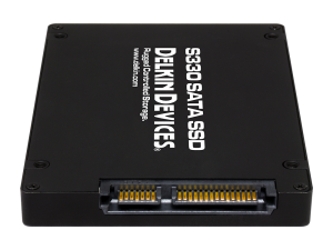
Serial ATA was introduced in 2003. It evolved from PATA, and shortly after its introduction replaced PATA in PCs and other systems.
SATA SSD has several advantages over the Parallel PATA hard drives developed in the 1980s. SATA cables are thinner, more flexible and smaller than the ribbon cables required for conventional PATA hard drives.
Setting SATA Controller Modes
Serial ATA hard drives connect to a computer’s motherboard via SATA Controller hardware that manages the flow of data. Putting SATA in IDE mode means the hard drive is recognized as a PATA device — a situation that provides better compatibility with older hardware, but comes with the tradeoff of lower performance.
Setting a SATA controller to Advanced Host Controller Interface (AHCI) offers higher performance than IDE mode, and enables features such as Hot Swapping on SATA drives. The redundant array of independent disk (RAID) mode supports both AHCI functions and RAID data protection features.
Technical Differences Between SATA and PATA
The SATA SSD transport layer differs from PATA drives, in which data bits are delivered simultaneously across a 40/80 -pin-wide ribbon cable. PATA is Half Duplex, meaning transmit and receive cannot occur at the same time. As its name suggests, a Serial ATA drive transfers data in serial fashion. Data is moved one bit at a time between a SATA drive and its host, using a seven-pin data cable and 15-pin power cable. The SATA cable results in a higher signaling rate, which corresponds to faster throughput of data. SATA is full duplex, differential, with a transmit pair and receive pair.
Standard SATA connector, data segment
| Pin # | Mating | Function | |
| 1 | 1st | Ground | |
| 2 | 2nd | A+ (transmit) | |
| 3 | 2nd | A− (transmit) | |
| 4 | 1st | Ground | |
| 5 | 2nd | B− (receive) | |
| 6 | 2nd | B+ (receive) | |
| 7 | 1st | Ground | |
| — | Coding notch | ||
The SATA standard defines a data cable with seven conductors (three grounds and four active data lines in two pairs) and 8 mm wide wafer connectors on each end. SATA cables can have lengths up to (3.3 ft.), and connect one motherboard socket to one hard drive. PATA ribbon cables, in comparison, connect one motherboard socket to one or two hard drives, carry either 40 or 80 wires, and are limited to 18 in length by the PATA specification. However, cables up to 35 in are readily available. Thus, SATA connectors and cables are easier to fit in closed spaces and reduce obstructions to air flow cooling. Although they are more susceptible to accidental unplugging and breakage than PATA, users can purchase cables that have a locking feature, whereby a small (usually metal) spring holds the plug in the socket. This rarely an issue though.
SATA connectors may be straight, right-angled, or left angled. Angled connectors allow lower-profile connections. Right-angled (also called 90-degree) connectors lead the cable immediately away from the drive, on the circuit-board side. Left-angled (also called 270-degree) connectors lead the cable across the drive towards its top.
One of the problems associated with the transmission of data at high speed over electrical connections is described as noise (Common mode and differential), which is due to electrical coupling between data circuits and other circuits. As a result, the data circuits can both affect other circuits and be affected by them. Designers use a number of techniques to reduce the undesirable effects of such unintentional coupling. One such technique used in SATA links is differential signaling. This is an enhancement over PATA, which uses single ended. The use of fully shielded twin-ax conductors, with multiple ground connections, for each differential pair improves isolation between the channels and reduces the chances of lost data in difficult electrical environments.
Differential transmission has a very high common mode rejection. Thus, common mode noise is cancelled. This allow longer cable runs in noisy environments.
Power Connectors
Standard Connector
Standard connector, power segment
| Pin # | Mating | Function | |
| — | Coding notch | ||
| 1 | 3rd | 3.3 V Power | |
| 2 | 3rd | ||
| 3 | 2nd | Enter/exit Power Disable (PWDIS) mode (3.3 V Power, Pre-charge prior to SATA 3.3) | |
| 4 | 1st | Ground | |
| 5 | 2nd | ||
| 6 | 2nd | ||
| 7 | 2nd | 5 V Power, Pre-charge | |
| 8 | 3rd | 5 V Power | |
| 9 | 3rd | ||
| 10 | 2nd | Ground | |
| 11 | 3rd | Staggered Spin Up/activity | |
| 12 | 1st | Ground | |
| 13 | 2nd | 12 V Power, Pre-charge | |
| 14 | 3rd | 12 V Power | |
| 15 | 3rd | ||
SATA specifies a different power connector than the four-pin used on PATA device. It is a wafer-type connector, like the SATA data connector, but much wider (fifteen pins versus seven) to avoid confusion between the two. Some early SATA drives included the four-pin Molex power connector together with the new fifteen-pin connector, but most SATA drives now have only the latter.
The new SATA power connector contains many more pins for several reasons:
- 3V is supplied along with the traditional 5V and 12V supplies. However, very few drives actually use it, so they may be powered from a four-pin Molex connector with an adapter.
- Pin 3 in SATA revision 3.3 has been redefined as PWDIS and is used to enter and exit the POWER DISABLE mode for compatibility with SAS specification. If Pin 3 is driven HIGH (2.1–3.6 V max), power to the drive circuitry is disabled. Drives with this feature do not power up in systems designed to SATA revision 3.1 or earlier. This is because Pin 3 driven HIGH prevents the drive from powering up.
- To reduce impedance and increase current capability, each voltage is supplied by three pins in parallel, though one pin in each group is intended for pre-charging (see below). Each pin should be able to carry 1.5 A.
- Five parallel pins provide a low-impedance ground connection.
- Two ground pins and one pin for each supplied voltage support hot plug pre-charging. Ground pins 4 and 12 in a hot-swap cable are the longest, so they make contact first when the connectors are mated. Drive power connector pins 3, 7, and 13 are longer than the others, so they make contact next. Drives use them to charge its internal bypass capacitors through current-limiting resistances. Finally, the remaining power pins make contact, bypassing the resistances and providing a low-impedance source of each voltage. This two-step mating process avoids glitches to other loads and possible arcing or erosion of the SATA power-connector contacts.
- Pin 11 can function if needed or can be left open. It is an open-collector signal, which may be pulled down by the connector or the drive. If pulled down at the connector (as it is on most cable-style SATA power connectors), the drive spins up as soon as power is applied. If left floating, the drive waits until it is spoken to. This prevents many drives from spinning up simultaneously, which might draw too much power. The pin is also pulled low by the drive to indicate drive activity. This may be used to give feedback to the user through an led.
Passive adapters are available that convert a four-pin PATA power connector to a SATA power connector, providing the 5V and 12V lines available on the Molex connector, but not 3.3 V. There are also four-pin Molex-to-SATA power adapters that include electronics to additionally provide the 3.3 V power supply. However, most drives do not use the 3.3 V power line.
Slimline Connector
Slimline connector, power segment
| Pin # | Mating | Function | |
| — | Coding notch | ||
| 1 | 3rd | Device presence | |
| 2 | 2nd | 5 V Power | |
| 3 | 2nd | ||
| 4 | 2nd | Manufacturing diagnostic | |
| 5 | 1st | Ground | |
| 6 | 1st | ||
SATA 2.6 is the first revision that defined the slimline connector, intended for smaller form-factors such as notebook optical drives. Pin 1 of the slimline signal connector, denoting device presence, is shorter than the others to allow hot-swapping. The slimline signal connector is identical and compatible with the standard version, while the power connector is reduced to six pins so it supplies only +5 V, and not +12V or +3.3V.
Low-cost adapters exist to convert from standard SATA to slimline SATA.
SATA Functional Description
The SATA specification defines three distinct protocol layers: physical, link, and transport.
Physical Layer
The physical layer defines SATA’s electrical and physical characteristics (such as cable dimensions and parasitics, driver voltage level and receiver operating range), as well as the physical coding subsystem (bit-level encoding, device detection on the wire, and link initialization).
Physical transmission uses differential signaling. The SATA PHY contains a transmit pair and receive pair. When the SATA-link is not in use, the transmitter allows the transmit pins to float to their common-mode voltage level. When the SATA-link is either active or in the link-initialization phase, the transmitter drives the transmit pins at the specified differential voltage (1.5V in SATA/I).
SATA physical coding uses a line encoding system known as 8b/10b This scheme serves multiple functions required to sustain a differential serial link. First, the stream contains necessary synchronization information that allows the SATA host/drive to extract the clock. Note the SATA link has no clock line. The 8b/10b encoded sequence embeds periodic edge transitions to allow the receiver to achieve bit-alignment without the use of a separately transmitted reference clock waveform. The sequence also maintains a neutral bitstream, which lets transmit drivers and receiver inputs be AC Coupled. Generally, the actual SATA signaling is half-duplex, meaning that it can only read or write data at any one time, although Full Duplex operation is physically present.
Also, SATA uses some of the special characters defined in 8b/10b. The PHY layer uses the comma character to maintain symbol-alignment. A specific four-symbol sequence, the ALIGN primitive, is used for clock rate-matching between the two devices on the link. Other special symbols communicate flow control information produced and consumed in the higher layers (link and transport).
Separate point-to-point AC-coupledLVDS) links are used for physical transmission between host and drive.
The Physical layer is responsible for detecting the other SATA/device on a cable, and link initialization. During the link-initialization process, the PHY is responsible for locally generating special out-of-band signals by switching the transmitter between electrical-idle and specific 10b-characters in a defined pattern, negotiating a mutually supported signaling rate (1.5, 3.0, or 6.0 Gbit/s), and finally synchronizing to the far-end device’s PHY-layer data stream. During this time, no data is sent from the link-layer.
Once link-initialization has completed, the link-layer takes over data-transmission, with the PHY providing only the 8b/10b conversion before bit transmission.
Link Layer
After the PHY-layer has established a link, the link layer is responsible for transmission and reception of Frame Information Structures (FISs) over the SATA link. FISs are packets containing control information or payload data. Each packet contains a header (identifying its type), and payload whose contents are dependent on the type. The link layer also manages flow control over the link.
Transport Layer
Layer number three in the serial ATA specification is the transport layer. This layer has the responsibility of acting on the frames and transmitting/receiving the frames in an appropriate sequence. The transport layer handles the assembly and disassembly of FIS structures, which includes, for example, extracting content from register FISs into the task-file and informing the command layer. In an abstract fashion, the transport layer is responsible for creating and encoding FIS structures requested by the command layer, and removing those structures when the frames are received.
When DMA data is to be transmitted and is received from the higher command layer, the transport layer appends the FIS control header to the payload, and informs the link layer to prepare for transmission. The same procedure is performed when data is received, but in reverse order. The link layer signals to the transport layer that there is incoming data available. Once the data is processed by the link layer, the transport layer inspects the FIS header and removes it before forwarding the data to the command layer. In the end, what is left parallels the PATA type register based information.
Topology
SATA topology: host (H), multiplier (M), and device (D)
SATA uses a point-to-point architecture. The physical connection between a controller and a storage device is not shared among other controllers and storage devices. SATA defines multipliers, which allows a single SATA controller port to drive up to fifteen storage devices. The multiplier performs the function of a hub; the controller and each storage device is connected to the hub.
Modern PC systems have SATA controllers built into the motherboard, typically featuring two to eight ports. Additional ports can be installed through add-in SATA host adapters (available in variety of bus-interfaces: USB, PCI, PCIe).
Backward and Forward Compatibility
SATA and PATA
At the hardware interface level, SATA and PATA devices are completely incompatible: they cannot be interconnected without an adapter.
At the application level, SATA devices can be specified to look and act like PATA/IDE devices.
Many motherboards offer a “Legacy Mode” option, which makes SATA drives appear to the OS like PATA drives on a standard controller. This Legacy Mode eases OS installation by not requiring that a specific driver be loaded during setup, but sacrifices support for some (vendor specific) features of SATA. Legacy Mode often if not always disables some of the boards’ PATA or SATA ports, since the standard PATA controller interface supports only four drives. (Often, which ports are disabled is configurable.)
The common heritage of the ATA command set has enabled the proliferation of low-cost PATA to SATA bridge chips. Bridge chips were widely used on PATA drives (before the completion of native SATA drives) as well in standalone converters. When attached to a PATA drive, a device-side converter allows the PATA drive to function as a SATA drive. Host-side converters allow a motherboard PATA port to connect to a SATA drive.
The market has produced powered enclosures for both PATA and SATA drives that interface to the PC through USB, Firewire or eSATA, with the restrictions noted above. PCI cards with a SATA connector exist that allow SATA drives to connect to legacy systems without SATA connectors.
Still in use today, CF cards are connected to CPUs using SATA to PATA bridge chip.
SATA Versions
The designers of SATA standard as an overall goal aimed for backward and forward with future revisions of the SATA standard. To prevent interoperability problems that could occur when next generation SATA drives are installed on motherboards with standard legacy SATA 1.5 Gbit/s host controllers, many manufacturers have made it easy to switch those newer drives to the previous standard’s mode.
SATA Standards and Revisions
The technical specifications governing Serial ATA device interfaces are authored by the nonprofit SATA-IO industry consortium. The consortium has made several revisions to SATA standards to reflect increased data transfer speeds.
- SATA Revision 1.0 devices were widely used in personal desktop and office computers, configured from PATA drives joined together in a master/slave configuration. SATA Revision 1 devices topped out at a transfer rate of 1.5 Gb/S or 187.5 MB/S.
- SATA Revision 2.0 devices doubled the transfer speed to 3.2 Gb/s or 400MB/s with the inclusion of port multipliers, port selectors and improved queuing.
- SATA Revision 3.0 interfaces support drive transfer rates up to 6 Gbps. SATA Revision 3 drives are back compatible with SATA Revision 1.0 and SATA Revision 2.0 devices, albeit with a lower transfer speed.
- SATA Revision 3.1 is an intermediate revision that added final design requirements for SATA Universal Storage Module for consumer-based portable storage applications.
- SATA Revision 3.2 added a specification known as SATA Express (SATAe), which supports simultaneous use of SATA ports and PCI Express (PCIe) lanes.
SATA Design Specs for Flash Storage
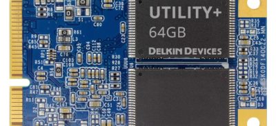
In 2009, the SATA-IO consortium unveiled the mSATA for small form solid-state drives SSDs. The M originally stood for mini, but that designation is no longer made and the specification is referred to as mSATA. An mSATA device is a Flash drive that conforms to the SATA-IO protocol specification and is mainly used in laptops, and other portable computing devices. The mSATA specification maps Serial ATA signals to an internally mounted PCIe card in a computer’s motherboard.
CFast SATA
The CF association defined a SATA version of CF card. This CF card is not compatible with standard CF card slots. Its use is so far not wide spread.
SATA Modes of Operation
In the PC world, SATA devices and device drivers can operate in either IDE mode, or AHCI mode. Using IDE mode makes the drive appear as a PATA device, at the sacrifice of speed. AHCI mode is by far the mode used.
AHCI
AHCI stands for Advance Host Controller Interface. AHCI is a hardware mechanism that allows software to communicate with Serial ATA (SATA) devices (such as host bus adapters) that are designed to offer features not offered by Parallel ATA (PATA) controllers, such as hot-plugging and native command queuing (NCQ). The specification details a system memory structure for computer hardware vendors in order to transfer data between system memory and the device.
Most SATA controllers can enable AHCI either separately or in conjunction with RAID support. Intel recommends choosing RAID mode on their motherboards (which also enables AHCI) rather than the plain AHCI/SATA mode for maximum flexibility, due to the issues caused when the mode is switched once an operating system has already been installed.
AHCI is fully supported out of the box for Microsoft Windows and the Linux operating system including Apple OS.
Advantages of AHCI
- Hot-Plugging
- Native Command Queuing (might improve computer/system/hard disk responsiveness, especially in multi-tasking environment, such as in Real-Time embedded applications.
NCQ
In principle, Native Command Queuing is relatively simple. It allows the drive to execute write /read commands that are transmitted randomly in order to optimize the movement of the reading head.
Speed is increased but there is also an impact on power consumption and noise level which is reduced. Of course, applications don’t have to work simultaneously and don’t have to wait for the previous result to send the next command. This of course isn’t always possible. Another possibility in using NCQ is multitasking in the case where you run two very heavy simultaneous drive access applications.
To better explain this situation, imagine an elevator, in which two people enter simultaneously on the ground floor. The first pushes the 12th floor button and the second the 2nd floor. It would be counterproductive to go to the 12th floor and then to the 2nd floor. The principle of NCQ was already in the ATA (PATA)norm since 1997 with TCQ (Tagged Command Queuing). This heavier protocol could sometimes lead to significant performance losses in the case of low loads (no or very little command reorganization to do) and has been integrated in a limited number of controllers. This was not in large use in PATA based systems.
For NCQ to be enabled, it must be supported and turned on in the SATA host bus adapter and in the hard drive itself. The appropriate driver must be loaded into the operating system to enable NCQ on the host bus adapter. All current chipsets support the Advanced Host Controller Interface (AHCI), which allows a generic driver supplied by the operating system to control them and enable NCQ. In fact, newer mainstream Linux kernels support AHCI natively. The best way to turn AHCI on is though the BIOS. All PCs today have AHCI turned on as the default SATA mode.
All current systems use AHCI. The hot-plugging is a requirement for using RAID. RAID is used in all Servers especially Enterprise.
Contact
Article Contributor:
Carmine C. Cupani, MSEE
CTech Electronics LLC
 Login
Login Register


