Technical Guide for CompactFlash (CF) and Secure Digital (SD) Cards
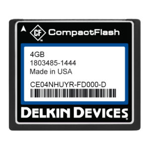
Industrial CF and SD cards are the most common Flash storage form factors in industrial applications. CompactFlash (CF) became the most successful of the early memory card formats, surpassing miniature and Smart media cards. Formats such as MMC/SD memory cards are smaller than CF, while offering comparable capacity and speed.
Traditional CF cards use the Parallel ATA (PATA) interface, but in 2008, a variant of CompactFlash, CFast was announced. CFast (also known as CompactFast) is based on the Serial ATA (SATA) interface.
There are two main subdivisions of CF cards, 3.3 mm thick type I and 5 mm-thick type II (CF2). The type II slot is used by miniature hard drives and in some specialty cameras, but is not as common. There are four main card speeds: original CF, CF High Speed (using CF+/CF2.0), faster CF 3.0 standard and the faster CF 4.0 standard adopted as of 2007. We now have CF 6.1, which introduces the fastest transfer speeds yet, using Ultra DMA 7 (UDMA 7)
CF cards can be used directly in a PC card slot with a plug-in adapter, used as an ATA (IDE) or PCMCIA storage device with a passive adapter or with a reader. Since the CF card is based on the PATA/IDE interface, it can easily be put on an PATA/IDE disk interface, as a Master or Slave device. Hence the CF card can serve as a disk drive in a Legacy PC using the IDE interface. This is because the CF card has a TRUE IDE mode, which allows the CF card to function exactly as a PATA/IDE drive. This mode is entered when the card has pin 9 grounded on the 50 pin connector when power is applied. When is TRUE IDE mode the CF card is not hot swappable. The passive adapter takes care of grounding pin 9.
CF Technical Description
The CompactFlash interface is a 50-pin subset of the 68-pin PCMCIA connector. “It can be easily slipped into a passive 68-pin PCMCIA Type II to CF Type I adapter.The interface operates, depending on the state of mode pin 9 on power-up, as either a 16-bit PC Card Memory or I/O mode card, or as an IDE/PATA Disk via TRUE IDE mode.
CF IDE mode defines an interface that is Physically smaller than, but electrically identical to the PATA/IDE interface. The CF device contains an Advanced Technology Attachment|ATA controller mode and appears to the host device as if it were a hard disk. CF devices must operate at 3.3 volts or 5 volts, and can be swapped from system to system. CF (in TRUE IDE mode) supports cylinder-head-sector| (C-H-S) and 28-bit logical block addressing (LBA 28). CF 5.0 introduced support for LBA-48 addressing. CF cards with flash memory are able to cope with extremely rapid changes in temperature. Industrial CF cards can operate at a range of -40° to +85° C.
Performance
The CF Interface is basically a Parallel ATA interface transferring 8 or 16 bit data in standard Memory and I/O modes or in TRUE IDE mode. Ultra DMA capable, these cards are capable of very high data transfer rates, provided the controller mapping is efficient. Usually page based mapping is used in the higher end cards.
CompactFlash speed can be specified in “x” ratings, such as 8x, 20x, 133x. This is the same system used for CD-ROM and indicates the maximum transfer rate in the form of a multiplier based on the original audio CD data transfer rate, which is 150 kByte/s.
S = K * 150 KB/S
where ‘S = transfer speed, ”K” = speed rating. For example, 133x rating means transfer speed of: 133 x .15MByte/s = 19.95MB/s.
The X ratings aren’t seen often anymore. Manufacturers are now placing the speed ratings on cards.
These are manufacturer speed ratings. Actual transfer speed may be higher, or lower, than shown on the card depending on several factors. The speed rating quoted is almost always the sequential read speed, while write speeds are often slower.
Modern UDMA-7 CompactFlash Cards provide data rates up to 145MB/S.
As a note, the USB 2.0 interface is limited to 35 MB/s and lacks bus mastering hardware, USB 2.0 implementation results in slower access. So testing speeds for CF on a USB 2.0 card reader is not recommended. USB 3.0 provides for higher speeds, so testing on these readers is better. However not all card readers use ULTRA DMA. The best speed tests are seen using a PATA/IDE bus capable of operating in high ULTRA DMA modes, using a short 80 conductor ribbon cable in CF to IDE adapter capable of using Ultra DMA.
Alternatively a PATA to SATA adapter can be used. These generally use a bridge chip which is capable of Ultra DMA modes. This is when the true card capability can be seen.
CF Use in Embedded Systems
CF card us in embedded systems, such as routers has been very popular even in the present. Legacy routers almost always contain CF cards. Direct connection of the 50 pin parallel bus to a CPU is not practical, although it was done in the old legacy systems, at a time when PATA drives were common. With the advent of Serial ATA (SATA), and most CPUs having a SATA port available, The CF card could be connected to the CPU using a CF to SATA bridge chip. This should allow full potential of the CF card to be realized.
On a standard CF type 1, there is a physical limitation on the number of Flash packages that can be placed on the PCB. (4) 48 pin packages are the limit. Therefore, card capacity is limited by this and the density of each Flash package. Another way to increase capacity is by using bonded die on a substrate. This is expensive and only makes sense in high end applications, not consumer products.
Using high capacity MLC or TLC devices, densities of 1TB or higher are possible. For better reliability 3D TLC based NAND can be used. Capacities of 256GB and 512GB are common.
Using higher density BGA package Flash can be a consideration for increasing density.
However, as we shall see the market is moving toward SDHC and SDXC technologies that show higher capacity and the same or higher than CF, especially using UHSII.
File Systems for CF Cards
A factory preformatted CF card is file system agnostic. An MBR is placed at LBA0 where the bios can detect the card. At that point, the card can be high level formatted with any file system. By far the most popular file systems used are from the Windows OS. Fat 32 and NTFS are popular and used in PCs and many SLR cameras and audio devices. Additionally, higher end CF cards support the TRIM function which optimized use of Flash-based devices. Linux OS Apple OS Journaled file systems can also be installed. This is typical in embedded systems such as routers.
Higher end CF cards support the secure ATA command set, the military security command set (an extension to the ATA specification) commands, SMART commands (to monitor card health) and HPA (Host Protected Area). These features are there to support Industrial and critical applications.
It is important to select a CF card vendor for critical applications that can support the addition of customer specific functions, as well as having support for solving compatibility issues should they arise.
SD/SDHC/SDXC Cards
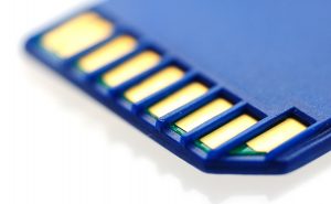
SD (Secure Digital) Card Basics
The SD card was spawned from the MMC (Multimedia) card. Very similar in electrical operation and form factor. The MMC card fell out of popularity in card format, and was replaced with the SD card. The MMC card has one big advantage over the SD card in its capability to transfer 8 bits per frame to the SD cards 4 bits. SD has CPRM secure keys for recorded content protection. However, it’s not used regularly, since royalties are charged.
MMC as an electrical entity is retained for use embedded MMC (e.MMC). Popular for use in embedded systems.
SD includes four card families available in three different sizes. The four families are:
Standard-Capacity (SDSC) to 2GB (extended to 4GB)
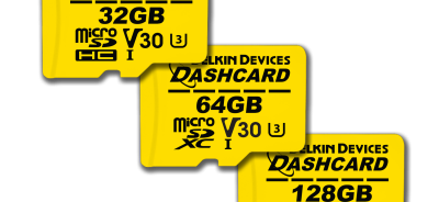
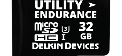
High-Capacity (SDHC) to 32GB
eXtended-Capacity (SDXC) to 2TB- (exFat)
SDIO (which combines I/O functions with data storage – (not part of the SD card specification)
The SD interface is completely different than that of the CF/ATA. Operating voltages are 3.3V or 1.8V, with SDXC having a lower voltage transfer capability on added pins. SD is a hybrid (Parallel/Serial) interface.
The SD card operates in SD card mode or SPI mode. Mode is determined at power up, by the host device driver, sending a special command into the card. SPI mode is a 1 bit mode, which is speed limited, but popular in micro-controller applications. SPI interfaces are common in the micro-controllers.
There are three basic transfer modes supported by SD:
SPI mode (one bit separate serial in and serial out bits)
1 bit SD mode Bidirectional (separate command/response line)
4-bit SD mode Bidirectional (separate command/response line)
Add to this the Ultra High Speed (UHS) modes, I, II and III.
Low speed cards support 0 to 400 kbit/s data rate and SPI and one-bit SD transfer modes. SD 2.0 cards support up to a theoretical 12.5 MB/s data rate in four-bit mode and 3.125 MB/s in SPI and one-bit SD modes. This is with a 25 MHz Host Clock. SD3.0 Upped clock speed to 50 MHz, with a resultant doubling of these speeds. Moving forward, speeds have increased significantly with UHS modes using DDR Clocking, much higher host clock speeds, and added low voltage differential signaling pins in the highest UHS modes.
SDHC
Version 2.0 also introduces a High-speed bus mode for both SDSC and SDHC cards, which doubles the original Standard Speed clock to produce 25MB/s.
SDHC host devices are required to accept older SD cards. However, older host devices do not recognize SDHC or SDXC memory cards, although some devices can do so through a firmware upgrade. Older Windows operating systems released before Windows 7 require patches or service packs to support access to SDHC cards.
SDXC
The Secure Digital eXtended Capacity (SDXC) format, announced in January 2009 and defined in version 3.01 of the SD specification, supports cards up to 2TB (2048GB), compared to a limit of 32GB for SDHC cards in the SD 2.0 specification. SDXC adopts Microsoft’s exFAT file system as a mandatory feature.
Version 3.01 also introduced the Ultra High Speed (UHS) bus for both SDHC and SDXC cards, with interface speeds from 50MByte/s to 104MByte/s for four-bit UHS-I bus.
Version 4.0, introduced in June 2011, allows speeds of 156MByte/s to 312MByte/s over the four-lane (two differential lanes) UHS-II bus, which requires an additional row of physical pins.[16]
Version 5.0 was announced in February 2016 at CP+ 2016, and added “Video Speed Class” ratings for UHS cards to handle higher resolution video formats like 8K.
Main of exFAT (as a FUSE module) in order to be able to mount exFAT-formatted volumes. However, SDXC cards can be reformatted to use any file system (such as ext2, UFS, or VFAT), alleviating the restrictions associated with exFAT availability.
Command interface
SD cards and host devices initially communicate through a synchronous one-bit interface, where the host device provides a clock signal that strobes single bits in and out of the SD card. The host device thereby sends 48-bit commands and receives responses. The card can signal that a response will be delayed, but the host device can abort the dialogue.
Through issuing various commands, the host device can:
Determine the type, memory capacity, and capabilities of the SD card.
Command the card to use a different voltage, different clock speed, or advanced electrical interface
Prepare the card to receive a block to write to the flash memory, or read and reply with the contents of a specified block.
The command interface is an extension of the MultiMediaCard (MMC) interface. SD cards dropped support for some of the commands in the MMC protocol, but added commands related to copy protection. By using only commands supported by both standards until determining the type of card inserted, a host device can accommodate both SD and MMC cards.
Electrical interface
All SD card families initially use a 3.3-volt electrical interface. On command, SDHC and SDXC cards can switch to 1.8 V operation.
At initial power-up or card insertion, the host device selects either the Serial Peripheral Interface (SPI) bus or the one-bit SD bus by the voltage level present on Pin 1. Thereafter, the host device may issue a command to switch to the four-bit SD bus interface, if the SD card supports it. For various card types, support for the four-bit SD bus is either optional or mandatory.
After determining that the SD card supports it, the host device can also command the SD card to switch to a higher transfer speed. Until determining the card’s capabilities, the host device should not use a clock speed faster than 400kHz. SD cards other than SDIO have a “Default Speed” clock rate of 25MHz. The host device is not required to use the maximum clock speed that the card supports. It may operate at less than the maximum clock speed to conserve power. Between commands, the host device can stop the clock entirely.
Achieving higher card speeds
The SD specification defines four-bit-wide transfers. (The MMC specification supports this and defines an eight-bit-wide mode; MMC cards with extended bits were not accepted by the market. Prove popular in e.MMC) Transferring several bits on each clock pulse improves the card speed. Advanced SD families have also improved speed by offering faster clock frequencies and double data rate DDR in a high-speed differential interface (UHS-II).
File systems
Like other types of flash memory card, an SD card of any SD family is a block-addressable storage device, in which the host device can read or write fixed-size blocks by specifying their block number. (LBA/SECTOR)
MBR and FAT
Most SD cards ship preformatted with one or more MBR partitions, where the first or only partition contains a file system. This lets them operate like the hard disk of a personal computer. Per the SD card specification, an SD card is formatted with MBR and the following file system:
For SDSC cards:
Capacity of less than 32,680 logical sectors (smaller than 16 MB): FAT12 with partition type 01h.
Capacity of 32,680 to 65,535 logical sectors (between 16MB and 32MB): FAT16 with partition type 04h.
Capacity of at least 65,536 logical sectors (larger than 32MB): FAT16B with partition type 06h.
For SDHC cards:
Capacity of less than 16,450,560 logical sectors (smaller than 7.8 GB): FAT32 with partition type 0Bh.
Capacity of at least 16,450,560 logical sectors (larger than 7.8 GB): FAT32 with partition type 0Ch.
For SDXC cards:
exFAT with partition type 07h – Window proprietary.
Most consumer products that take an SD card expect that it is partitioned and formatted in this way. Universal support for FAT12, FAT16, FAT16B, and FAT32 allows the use of SDSC and SDHC cards on most host computers with a compatible SD reader, to present the user with the familiar method of named files in a hierarchical directory tree.
On such SD cards, standard utility programs such as Mac OS X’s “Disk Utility” or Windows’ SCANDISK can be used to repair a corrupted filing system and sometimes recover deleted files. Defragmentation tools for FAT file systems may be used on such cards. The resulting consolidation of files may provide a marginal improvement in the time required to read or write the file,[104] but not an improvement comparable to defragmentation of hard drives, where storing a file in multiple fragments requires additional physical, and relatively slow, movement of a drive head. Moreover, defragmentation performs writes to the SD card that count against the card’s rated lifespan.
When reformatting an SD card with a capacity of at least 32MB (65536 logical sectors or more), but not more than 2GB, FAT16B with partition type 06 hours is recommended if the card is for a consumer device. (FAT16B is also an option for 4GB cards, but it requires the use of 64k clusters, which are not widely supported). FAT16B does not support cards above 4GB at all.
The SDXC specification mandates the use of Microsoft’s proprietary exFAT file system, which is supported only by some proprietary operating systems.
Because the host views the SD card as a block storage device, the card does not require MBR partitions or any specific file system. The card can be reformatted to use any file system the operating system supports. For example:
Under Windows, SD cards can be formatted using NTFS and, on later versions, exFAT.
Under macOS, SD cards can be partitioned as GUID devices and formatted with either HFS Plus or APFS file systems or still use exFAT.
Under Unix-like operating systems such as Linux or FreeBSD, SD cards can be formatted using the UFS, Ext2, Ext3, Ext4, btrfs, HFS Plus, Reiser FS or F2FS file system. Additionally, under Linux, HFS Plus file systems may be accessed for read/write if the “hfsplus” package is installed, and partitioned and formatted if “hfsprogs” is installed. (These package names are correct under Debian, Ubuntu etc., but may differ on other Linux distributions.)
Any recent version of the above can format SD cards using the UDF file system.
Additionally, as with live USB flash drives, an SD card can have an operating system installed on it. Computers that can boot from an SD card (either using a USB adapter or inserted into the computer’s flash media reader) instead of the hard disk drive may thereby be able to recover from a corrupted hard disk drive. Such an SD card can be write-locked to preserve the system’s integrity.
The SD Standard allows usage of only the above-mentioned Microsoft FAT file systems and any card produced in the market shall be preloaded with the related standard file system upon its delivery to the market. If any application or user re-formats the card with a non-standard file system the proper operation of the card, including interoperability, cannot be assured.
Power Consumption
The power consumption of SD cards varies by its speed mode, manufacturer and model.
During transfer, it may be in the range of (20–100 mA at a supply voltage of 3.3 V).
Modern UHS-II cards can consume up to 2.88 W, if the host device supports bus speed mode SDR104 or UHS-II. Minimum power consumption in the case of a UHS-II host is 0.72 W.
Like most memory card formats, SD is covered by numerous patents and trademarks. Royalties for SD card licensees are imposed for manufacture and sale of memory cards and host adapters (US$1,000/year plus membership at US$1,500/year), but SDIO cards can be made without royalties.
Early versions of the SD specification were available only after agreeing to a non-disclosure agreement (NDA) that prohibited development of an open source driver. However, the system was eventually reverse-engineered, and free software drivers provided access to SD cards that did not use DRM. Since then, the SDA has provided a simplified version of the specification under a less restrictive license. Although most open-source drivers were written before this, it has helped to solve compatibility issues.
In 2006, the SDA released a simplified version of the specification of the host controller interface (as opposed to the specification of SD cards) and later also for the physical layer, ASSD extensions, SDIO, and SDIO Bluetooth Type-A, under a disclaimers agreement. [116] Again, most of the information had already been discovered and Linux had a fully free driver for it. Still, building a chip conforming to this specification caused the One Laptop per Child project to claim “the first truly Open Source SD implementation, with no need to obtain an SDI license or sign NDAs to create SD drivers or applications.”
The proprietary nature of the complete SD specification affects embedded systems, laptop computers, and some desktop computers; many desktop computers do not have card slots, instead using USB-based card readers if necessary. These card readers present a standard USB mass storage interface to memory cards, thus separating the operating system from the details of the underlying SD interface. However, embedded systems (such as portable music players) usually gain direct access to SD cards and thus need complete programming information. Desktop card readers are themselves embedded systems; their manufacturers have usually paid the SDA for complete access to the SD specifications. Many notebook computers now include SD card readers not based on USB; device drivers for these essentially gain direct access to the SD card, as do embedded systems.
The SPI-bus interface mode is the only type that does not require a host license for accessing SD cards.
Comparison to other flash memory formats
Size comparison of various flash cards: SD, CompactFlash, MMC, xD
Overall, SD is less open than CompactFlash or USB flash memory drives. Those open standards can be implemented without paying for licensing, royalties, or documentation. (CompactFlash and USB flash drives may require licensing fees for the use of the SDA’s trademarked logos.)
However, SD is much more open than Memory Stick, for which no public documentation nor any documented legacy implementation is available. All SD cards can be accessed freely using the well-documented SPI bus.
Comparison of technical features of CF and SD cards
From the above information, densities of both CF and SD cards are roughly similar. CF cards under CF 6.0, using UDMA 7 are very fast at 145 MB/S. SDHC cards using UHS II can produce speeds of 312MB/S. This using 2 low voltage differential lanes on added pins.
Many embedded systems are moving to SDHC, or Embedded MMC and SD. e.MMC uses custom modules that are customer specific. There are or types of connectors that are being used by router companies, and are becoming popular. Modules are favored over soldered parts, since they can be formatted outside the embedded platform (Important for production), and swapped out in an easier manner.
Having said that we believe CF connected with a SATA to PATA bridge such as the Marvel, will remain popular. CPUs all have SATA ports and device drivers are proven.
Please contact Delkin Devices and we’ll answer any technical questions you may have about Industrial CF or Industrial SD cards.
Contact
Article Contributor:
Carmine C. Cupani, MSEE
CTech Electronics LLC
 Login
Login Register


